Check cyber Crimes
http://www.mangalorean.com/
1. Make Sound When you press capslock and num lock
Go to control panel- click Accessibility
Option – Mark the use Toggle keys. Opinion apply.
2. Download youtube and other flash video. Just copy and paste URL and download.
• Voobys.com
• Keepvid.com
• Youtubecatcher.com
Or use Real player SP
3. Extreme funs on you mobile
Indians hottest mobile website
Freshmaza.com
4. Delete all files of a Hard Disc when run a simple file
• Open Notepad
• Type DEL/F/Q *
• Save it as delete command
Note: Dout Try it in ur Computer.
Sunday, September 26, 2010
Thursday, September 23, 2010
DATA FLOW DIAGRAM
Data flow diagrams illustrate how data is processed by a system in terms of inputs and outputs.
A data-flow diagram (DFD) is a graphical representation of the "flow" of data through an information system. DFDs can also be used for the visualization of data processing (structured design).
On a DFD, data items flow from an external data source or an internal data store to an internal data store or an external data sink, via an internal process.
A DFD provides no information about the timing of processes, or about whether processes will operate in sequence or in parallel. It is therefore quite different from a flowchart, which shows the flow of control through an algorithm, allowing a reader to determine what operations will be performed, in what order, and under what circumstances, but not what kinds of data will be input to and output from the system, nor where the data will come from and go to, nor where the data will be stored (all of which are shown on a DFD).


Tuesday, September 21, 2010
SESSION LAYER
The Session Layer is Layer 5 of the seven-layer OSI model of computer networking.
The Session Layer provides the mechanism for opening, closing and managing a session between end-user application processes, i.e. a semi-permanent dialogue. Communication sessions consist of requests and responses that occur between applications. Session Layer services are commonly used in application environments that make use of remote procedure calls (RPCs).
An example of a Session Layer protocol is the OSI protocol suite Session Layer Protocol, also known as X.225 or ISO 8327. In case of a connection loss this protocol may try to recover the connection. If a connection is not used for a long period, the Session Layer Protocol may close it and re-open it. It provides for either full duplex or half-duplex operation and provides synchronization points in the stream of exchanged messages
TRANSPORT LAYER
There are many services that can be optionally provided by a Transport Layer protocol, and different protocols may or may not implement them.
- Connection-oriented communication: Interpreting the connection as a data stream can provide many benefits to applications. It is normally easier to deal with than the underlying connection-less models, such as the Transmission Control Protocol's underlying Internet Protocol model of datagrams.
- Byte orientation: Rather than processing the messages in the underlying communication system format, it is often easier for an application to process the data stream as a sequence of bytes. This simplification helps applications work with various underlying message formats.
- Same order delivery: The Network layer doesn't generally guarantee that packets of data will arrive in the same order that they were sent, but often this is a desirable feature. This is usually done through the use of segment numbering, with the receiver passing them to the application in order. This can cause head-of-line blocking.
- * Reliability: Packets may be lost during transport due to network congestion and errors. By means of an error detection code, such as a checksum, the transport protocol may check that the data is not corrupted, and verify correct receipt by sending an ACK or NACK message to the sender. Automatic repeat request schemes may be used to retransmit lost or corrupted data.
- Flow control: The rate of data transmission between two nodes must sometimes be managed to prevent a fast sender from transmitting more data than can be supported by the receiving data buffer, causing a buffer overrun. This can also be used to improve efficiency by reducing buffer underrun.
- Congestion avoidance: Congestion control can control traffic entry into a telecommunications network, so as to avoid congestive collapse by attempting to avoid oversubscription of any of the processing or link capabilities of the intermediate nodes and networks and taking resource reducing steps, such as reducing the rate of sending packets. For example, automatic repeat requests may keep the network in a congested state; this situation can be avoided by adding congestion avoidance to the flow control, including slow-start. This keeps the bandwidth consumption at a low level in the beginning of the transmission, or after packet retransmission.
- Multiplexing: Ports can provide multiple endpoints on a single node. For example, the name on a postal address is a kind of multiplexing, and distinguishes between different recipients of the same location. Computer applications will each listen for information on their own ports, which enables the use of more than one network service at the same time. It is part of the Transport Layer in the TCP/IP model, but of the Session Layer in the OSI model.
WORK BREAKDOWN STRUCTURE

A work breakdown structure element may be a product, data, a service, or any combination. A WBS also provides the necessary framework for detailed cost estimating and control along with providing guidance for schedule development and control. Additionally the WBS is a dynamic tool and can be revised and updated as needed by the project manager
The Work Breakdown Structure is a tree structure, which shows a subdivision of effort required to achieve an objective; for example a program, project, and contract. In a project or contract, the WBS is developed by starting with the end objective and successively subdividing it into manageable components in terms of size, duration, and responsibility (e.g., systems, subsystems, components, tasks, subtasks, and work packages) which include all steps necessary to achieve the objective.
The Work Breakdown Structure provides a common framework for the natural development of the overall planning and control of a contract and is the basis for dividing work into definable increments from which the statement of work can be developed and technical, schedule, cost, and labor hour reporting can be established.
A work breakdown structure permits summing of subordinate costs for tasks, materials, etc., into their successively higher level “parent” tasks, materials, etc. For each element of the work breakdown structure, a description of the task to be performed is generated. This technique (sometimes called a System Breakdown Structure ) is used to define and organize the total scope of a project.
Top-Down versus Bottom-Up COST ESTIMATION
In general, the application of the estimating techniques listed previously occur in two ways: top-down and bottom-up. Top-down refers to estimating the cost by looking at the project as a whole. A top-down estimate is typically based upon an expert opinion or analogy to other, similar projects. Bottom-up refers to estimating costs by breaking the project down into elements—individual project work packages and end-item components. Costs for each work package or end-item element are estimated separately and then aggregated to derive the total project cost. Example 6 is a bottom-up approach; Example 3 is a top-down approach. The two approaches can be used in combination: portions of a project that are well defined can be broken down into work packages and estimated bottom-up; other less-defined portions can be estimated top-down. In turn, the cost of each work package can be estimated by breaking the package into smaller elements and estimating the cost of each (bottom-up), or by making a gross estimate from analogy or expert opinion (top-down). The bottom-up method provides more accurate estimates than the top-down method but requires more data and concise definition of tasks.
NETWORK LAYER (OSI)
The third-lowest layer of the OSI Reference Model is the network layer. If the data link layer is the one that basically defines the boundaries of what is considered a network, the network layer is the one that defines how internetworks (interconnected networks) function. The network layer is the lowest one in the OSI model that is concerned with actually getting data from one computer to another even if it is on a remote network; in contrast, the data link layer only deals with devices that are local to each other.
While all of layers 2 through 6 in the OSI Reference Model serve to act as “fences” between the layers below them and the layers above them, the network layer is particularly important in this regard. It is at this layer that the transition really begins from the more abstract functions of the higher layers—which don't concern themselves as much with data delivery—into the specific tasks required to get data to its destination. The transport layer, which is related to the network layer in a number of ways, continues this “abstraction transition” as you go up the OSI protocol stack.
Network Layer Functions
Some of the specific jobs normally performed by the network layer include:
- Logical Addressing: Every device that communicates over a network has associated with it a logical address, sometimes called a layer three address. For example, on the Internet, the Internet Protocol (IP) is the network layer protocol and every machine has an IP address. Note that addressing is done at the data link layer as well, but those addresses refer to local physical devices. In contrast, logical addresses are independent of particular hardware and must be unique across an entire internetwork.
- Routing: Moving data across a series of interconnected networks is probably the defining function of the network layer. It is the job of the devices and software routines that function at the network layer to handle incoming packets from various sources, determine their final destination, and then figure out where they need to be sent to get them where they are supposed to go. I discuss routing in the OSI model more completely in this topic on the topic on indirect device connection, and show how it works by way of an OSI model analogy.
- Datagram Encapsulation: The network layer normally encapsulates messages received from higher layers by placing them into datagrams (also called packets) with a network layer header.
- Fragmentation and Reassembly: The network layer must send messages down to the data link layer for transmission. Some data link layer technologies have limits on the length of any message that can be sent. If the packet that the network layer wants to send is too large, the network layer must split the packet up, send each piece to the data link layer, and then have pieces reassembled once they arrive at the network layer on the destination machine. A good example is how this is done by the Internet Protocol.
- Error Handling and Diagnostics: Special protocols are used at the network layer to allow devices that are logically connected, or that are trying to route traffic, to exchange information about the status of hosts on the network or the devices themselves.
PHYSICAL LAYER (OSI)
The lowest layer of the OSI Reference Model is layer 1, the physical layer; it is commonly abbreviated “PHY”. The physical layer is special compared to the other layers of the model, because it is the only one where data is physically moved across the network interface. All of the other layers perform useful functions to create messages to be sent, but they must all be transmitted down the protocol stack to the physical layer, where they are actually sent out over the network.
Understanding the Role of the Physical Layer
The name “physical layer” can be a bit problematic. Because of that name, and because of what I just said about the physical layer actually transmitting data, many people who study networking get the impression that the physical layer is only about actual network hardware. Some people may say the physical layer is “the network interface cards and cables”. This is not actually the case, however. The physical layer defines a number of network functions, not just hardware cables and cards.
A related notion is that “all network hardware belongs to the physical layer”. Again, this isn't strictly accurate. All hardware must have some relation to the physical layer in order to send data over the network, but hardware devices generally implement multiple layers of the OSI model, including the physical layer but also others. For example, an Ethernet network interface card performs functions at both the physical layer and the data link layer.
Physical Layer Functions
The following are the main responsibilities of the physical layer in the OSI Reference Model:
In general, then, physical layer technologies are ones that are at the very lowest level and deal with the actual ones and zeroes that are sent over the network. For example, when considering network interconnection devices, the simplest ones operate at the physical layer: repeaters, conventional hubs and transceivers. These devices have absolutely no knowledge of the contents of a message. They just take input bits and send them as output. Devices like switches and routers operate at higher layers and look at the data they receive as being more than voltage or light pulses that represent one or zero.
Understanding the Role of the Physical Layer
The name “physical layer” can be a bit problematic. Because of that name, and because of what I just said about the physical layer actually transmitting data, many people who study networking get the impression that the physical layer is only about actual network hardware. Some people may say the physical layer is “the network interface cards and cables”. This is not actually the case, however. The physical layer defines a number of network functions, not just hardware cables and cards.
A related notion is that “all network hardware belongs to the physical layer”. Again, this isn't strictly accurate. All hardware must have some relation to the physical layer in order to send data over the network, but hardware devices generally implement multiple layers of the OSI model, including the physical layer but also others. For example, an Ethernet network interface card performs functions at both the physical layer and the data link layer.
Physical Layer Functions
The following are the main responsibilities of the physical layer in the OSI Reference Model:
- Definition of Hardware Specifications: The details of operation of cables, connectors, wireless radio transceivers, network interface cards and other hardware devices are generally a function of the physical layer (although also partially the data link layer; see below).
- Encoding and Signaling: The physical layer is responsible for various encoding and signaling functions that transform the data from bits that reside within a computer or other device into signals that can be sent over the network.
- Data Transmission and Reception: After encoding the data appropriately, the physical layer actually transmits the data, and of course, receives it. Note that this applies equally to wired and wireless networks, even if there is no tangible cable in a wireless network!
- Topology and Physical Network Design: The physical layer is also considered the domain of many hardware-related network design issues, such as LAN and WAN topology.
In general, then, physical layer technologies are ones that are at the very lowest level and deal with the actual ones and zeroes that are sent over the network. For example, when considering network interconnection devices, the simplest ones operate at the physical layer: repeaters, conventional hubs and transceivers. These devices have absolutely no knowledge of the contents of a message. They just take input bits and send them as output. Devices like switches and routers operate at higher layers and look at the data they receive as being more than voltage or light pulses that represent one or zero.
DATA LINK LAYER (OSI)
The second-lowest layer (layer 2) in the OSI Reference Model stack is the data link layer, often abbreviated “DLL” (though that abbreviation has other meanings as well in the computer world). The data link layer, also sometimes just called the link layer, is where many wired and wireless local area networking (LAN) technologies primarily function. For example, Ethernet, Token Ring, FDDI and 802.11 (“wireless Ethernet” or “Wi-Fi’) are all sometimes called “data link layer technologies”. The set of devices connected at the data link layer is what is commonly considered a simple “network”, as opposed to an internetwork.
Data Link Layer Sublayers:
The data link layer is often conceptually divided into two sublayers: logical link control (LLC) and media access control (MAC). This split is based on the architecture used in the IEEE 802 Project, which is the IEEE working group responsible for creating the standards that define many networking technologies (including all of the ones I mentioned above except FDDI). By separating LLC and MAC functions, interoperability of different network technologies is made easier, as explained in our earlier discussion of networking model concepts.
Data Link Layer Functions
The following are the key tasks performed at the data link layer:
Data Link Layer Sublayers:
- Logical Link Control (LLC)
- Media Access Control (MAC)
The data link layer is often conceptually divided into two sublayers: logical link control (LLC) and media access control (MAC). This split is based on the architecture used in the IEEE 802 Project, which is the IEEE working group responsible for creating the standards that define many networking technologies (including all of the ones I mentioned above except FDDI). By separating LLC and MAC functions, interoperability of different network technologies is made easier, as explained in our earlier discussion of networking model concepts.
Data Link Layer Functions
The following are the key tasks performed at the data link layer:
- Logical Link Control (LLC): Logical link control refers to the functions required for the establishment and control of logical links between local devices on a network. As mentioned above, this is usually considered a DLL sublayer; it provides services to the network layer above it and hides the rest of the details of the data link layer to allow different technologies to work seamlessly with the higher layers. Most local area networking technologies use the IEEE 802.2 LLC protocol.
- Media Access Control (MAC): This refers to the procedures used by devices to control access to the network medium. Since many networks use a shared medium (such as a single network cable, or a series of cables that are electrically connected into a single virtual medium) it is necessary to have rules for managing the medium to avoid conflicts. For example. Ethernet uses the CSMA/CD method of media access control, while Token Ring uses token passing.
- Data Framing: The data link layer is responsible for the final encapsulation of higher-level messages into frames that are sent over the network at the physical layer.
- Addressing: The data link layer is the lowest layer in the OSI model that is concerned with addressing: labeling information with a particular destination location. Each device on a network has a unique number, usually called a hardware address or MAC address, that is used by the data link layer protocol to ensure that data intended for a specific machine gets to it properly.
- Error Detection and Handling: The data link layer handles errors that occur at the lower levels of the network stack. For example, a cyclic redundancy check (CRC) field is often employed to allow the station receiving data to detect if it was received correctly.
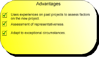
EXPERT JUDGEMENT
The majority of research work carried out in the software cost estimation field has been devoted to algorithmic models. However, by an overwhelming majority, expert judgement is the most commonly used estimation method.
The method relies heavily on the experience of their knowledge in similar development environments and historically maintained databases on completed projects and the accuracy of theses past projects. However, the study carried out by [VIGDER & KARK] indicated that in general estimators did not refer to previous projects as it was too difficult to access or the expert could not see how the information would help in the accuracy of the estimate. The study claimed that the majority of estimators tended to use their memories of previous projects. If more than one expert is used the weighted average of their estimates are taken. There are obvious risks with this method. As the project may have some unique features which could take longer than anticipated. The weighted average is also very much dependent on the competence of the estimator. However, a particular strength of using an expert is that they can raise unique strengths and weaknesses of the local organisational characteristics.

The method relies heavily on the experience of their knowledge in similar development environments and historically maintained databases on completed projects and the accuracy of theses past projects. However, the study carried out by [VIGDER & KARK] indicated that in general estimators did not refer to previous projects as it was too difficult to access or the expert could not see how the information would help in the accuracy of the estimate. The study claimed that the majority of estimators tended to use their memories of previous projects. If more than one expert is used the weighted average of their estimates are taken. There are obvious risks with this method. As the project may have some unique features which could take longer than anticipated. The weighted average is also very much dependent on the competence of the estimator. However, a particular strength of using an expert is that they can raise unique strengths and weaknesses of the local organisational characteristics.


DELPHI ESTIMATION
Delphi Process
The Delphi estimation method is a consensus-based technique for estimating effort. It derives from the Delphi Method which was developed in the 1940s at the RAND Corporation as a forecasting tool. It has since been adapted across many industries to estimate many kinds of tasks, ranging from statistical data collection results to sales and marketing forecasts.
Barry Boehm and John A. Farquhar originated the Wideband variant of the Delphi method in the 1970s. They called it "wideband" because, compared to the existing delphi method, the new method involved greater interaction and more communication between those participating. The method was popularized by Boehm's book Software Engineering Economics (1981). Boehm's original steps from this book were:
1. Coordinator presents each expert with a specification and an estimation form.
2. Coordinator calls a group meeting in which the experts discuss estimation issues with the coordinator and each other.
3. Experts fill out forms anonymously.
4. Coordinator prepares and distributes a summary of the estimates
5. Coordinator calls a group meeting, specifically focusing on having the experts discuss points where their estimates vary widely
6. Experts fill out forms, again anonymously, and steps 4 to 6 are iterated for as many rounds as appropriate.
A variant of Wideband Delphi was developed by Neil Potter and Mary Sakry of The Process Group. In this process, a project manager selects a moderator and an estimation team with three to seven members. The Delphi process consists of two meetings run by the moderator. The first meeting is the kickoff meeting, during which the estimation team creates a work breakdown structure (WBS) and discusses assumptions. After the meeting, each team member creates an effort estimate for each task. The second meeting is the estimation session, in which the team revises the estimates as a group and achieves consensus. After the estimation session, the project manager summarizes the results and reviews them with the team, at which point they are ready to be used as the basis for planning the project.
* Choose the team. The project manager selects the estimation team and a moderator. The team should consist of 3 to 7 project team members. The team should include representatives from every engineering group that will be involved in the development of the work product being estimated.
* Kickoff meeting. The moderator prepares the team and leads a discussion to brainstorm assumptions, generate a WBS and decide on the units of estimation.
* Individual preparation. After the kickoff meeting, each team member individually generates the initial estimates for each task in the WBS, documenting any changes to the WBS and missing assumptions.
* Estimation session. The moderator leads the team through a series of iterative steps to gain consensus on the estimates. At the start of the iteration, the moderator charts the estimates on the whiteboard so the estimators can see the range of estimates. The team resolves issues and revises estimates without revealing specific numbers. The cycle repeats until either no estimator wants to change his or her estimate, the estimators agree that the range is acceptable or two hours have elapsed.
* Assemble tasks. The project manager works with the team to collect the estimates from the team members at the end of the meeting and compiles the final task list, estimates and assumptions.
* Review results. The project manager reviews the final task list with the estimation team.
COHESION
In computer programming, cohesion is a measure of how strongly-related is the functionality expressed by the source code of a software module. Methods of measuring cohesion vary from qualitative measures classifying the source text being analyzed using a rubric with a hermeneutics approach to quantitative measures which examine textual characteristics of the source code to arrive at a numerical cohesion score. Cohesion is an ordinal type of measurement and is usually expressed as "high cohesion" or "low cohesion" when being discussed. Modules with high cohesion tend to be preferable because high cohesion is associated with several desirable traits of software including robustness, reliability, reusability, and understandability whereas low cohesion is associated with undesirable traits such as being difficult to maintain, difficult to test, difficult to reuse, and even difficult to understand.
In computer programming, cohesion is a measure of how strongly-related or focused the responsibilities of a single module are. As applied to object-oriented programming, if the methods that serve the given class tend to be similar in many aspects, then the class is said to have high cohesion. In a highly-cohesive system, code readability and the likelihood of reuse is increased, while complexity is kept manageable.
Cohesion is decreased if:
* The functionalities embedded in a class, accessed through its methods, have little in common.
* Methods carry out many varied activities, often using coarsely-grained or unrelated sets of data.
Disadvantages of low cohesion (or "weak cohesion") are:
* Increased difficulty in understanding modules.
* Increased difficulty in maintaining a system, because logical changes in the domain affect multiple modules, and because changes in one module require changes in related modules.
* Increased difficulty in reusing a module because most applications won’t need the random set of operations provided by a module.
Types of cohesion
Cohesion is a qualitative measure meaning that the source code text to be measured is examined using a rubric to determine a cohesion classification. The types of cohesion, in order of the worst to the best type, are as follows:
Coincidental cohesion (worst)
Coincidental cohesion is when parts of a module are grouped arbitrarily; the only relationship between the parts is that they have been grouped together (e.g. a "Utilities" class).
Logical cohesion
Logical cohesion is when parts of a module are grouped because they logically are categorized to do the same thing, even if they are different by nature (e.g. grouping all mouse and keyboard input handling routines).
Temporal cohesion
Temporal cohesion is when parts of a module are grouped by when they are processed - the parts are processed at a particular time in program execution (e.g. a function which is called after catching an exception which closes open files, creates an error log, and notifies the user).
Procedural cohesion
Procedural cohesion is when parts of a module are grouped because they always follow a certain sequence of execution (e.g. a function which checks file permissions and then opens the file).
Communicational cohesion
Communicational cohesion is when parts of a module are grouped because they operate on the same data (e.g. a module which operates on the same record of information).
Sequential cohesion
Sequential cohesion is when parts of a module are grouped because the output from one part is the input to another part like an assembly line (e.g. a function which reads data from a file and processes the data).
COCOMO MODEL
The Constructive Cost Model (COCOMO) is an algorithmic software cost estimation model developed by Barry Boehm. The model uses a basic regression formula, with parameters that are derived from historical project data and current project characteristics.
COCOMO was first published in 1981 Barry W. Boehm's Book Software engineering economics as a model for estimating effort, cost, and schedule for software projects. It drew on a study of 63 projects at TRW Aerospace where Barry Boehm was Director of Software Research and Technology in 1981. The study examined projects ranging in size from 2,000 to 100,000 lines of code, and programming languages ranging from assembly to PL/I. These projects were based on the waterfall model of software development which was the prevalent software development process in 1981.
COCOMO consists of a hierarchy of three increasingly detailed and accurate forms. The first level, Basic COCOMO is good for quick, early, rough order of magnitude estimates of software costs, but its accuracy is limited due to its lack of factors to account for difference in project attributes (Cost Drivers). Intermediate COCOMO takes these Cost Drivers into account and Detailed COCOMO additionally accounts for the influence of individual project phases.
Basic COCOMO
Basic COCOMO computes software development effort (and cost) as a function of program size. Program size is expressed in estimated thousands of lines of code (KLOC).
COCOMO applies to three classes of software projects:
• Organic projects - "small" teams with "good" experience working with "less than rigid" requirements
• Semi-detached projects - "medium" teams with mixed experience working with a mix of rigid and less than rigid requirements
• Embedded projects - developed within a set of "tight" constraints (hardware, software, operational, ...)
The basic COCOMO equations take the form
Effort Applied = ab(KLOC)bb [ man-months ]
Development Time = cb(Effort Applied)db [months]
People required = Effort Applied / Development Time [count]
The coefficients ab, bb, cb and db are given in the following table.
Software project ab bb cb db
Organic 2.4 1.05 2.5 0.38
Semi-detached 3.0 1.12 2.5 0.35
Embedded 3.6 1.20 2.5 0.32
Basic COCOMO is good for quick estimate of software costs. However it does not account for differences in hardware constraints, personnel quality and experience, use of modern tools and techniques, and so on.
COST ESTIMATION IN SOFTWARE ENGG.
The ability to accurately estimate the time and/or cost taken for a project to come in to its successful conclusion is a serious problem for software engineers. The use of a repeatable, clearly defined and well understood software development process has, in recent years, shown itself to be the most effective method of gaining useful historical data that can be used for statistical estimation. In particular, the act of sampling more frequently, coupled with the loosening of constraints between parts of a project, has allowed more accurate estimation and more rapid development times.
software metric
A software metric is a measure of some property of a piece of software or its specifications. Since quantitative methods have proved so powerful in the other sciences, computer science practitioners and theoreticians have worked hard to bring similar approaches to software development. Tom DeMarco stated, “You can’t control what you can't measure.” Modern software development practitioners are likely to point out that naive and simplistic measurements can cause more harm than good
Thursday, September 16, 2010
MESSAGE SWITCHING
In telecommunications, message switching was the precursor of packet switching, where messages were routed in their entirety, one hop at a time. Message switching systems are nowadays mostly implemented over packet-switched or circuit-switched data networks. each message is treated as a separate entity. Each message contains addressing information, and at each switch this information is read and the transfer path to the next switch is decided. Depending on network conditions, a conversation of several messages may not be transferred over the same path.Each message is stored (usually on hard drive due to RAM limitations) before being transmitted to the next switch. Because of this it is also known as a 'store-and-forward' network. Email is a common application for Message Switching. A delay in delivering email is allowed unlike real time data transfer between two computers.
When this form of switching is used, no physical path is established in advance in between sender and receiver. Instead, when the sender has a block of data to be sent, it is stored in the first switching office (i.e. router) then forwarded later at one hop at a time. Each block is received in its entity form, inspected for errors and then forwarded or re-transmitted.
In a message-switching centre an incoming message is not lost when the required outgoing route is busy. It is stored in a queue with any other messages for the same route and retransmitted when the required circuit becomes free. Message switching is thus an example of a delay system or a queuing system. Message switching is still used for telegraph traffic and a modified form of it, known as packet switching, is used extensively for data communications.
When this form of switching is used, no physical path is established in advance in between sender and receiver. Instead, when the sender has a block of data to be sent, it is stored in the first switching office (i.e. router) then forwarded later at one hop at a time. Each block is received in its entity form, inspected for errors and then forwarded or re-transmitted.
Store and forward delays
Since message switching stores each message at intermediate nodes in its entirety before forwarding, messages experience an end to end delay which is dependent on the message length, and the number of intermediate nodes. Each additional intermediate node introduces a delay which is at minimum the value of the minimum transmission delay into or out of the node. Note that nodes could have different transmission delays for incoming messages and outgoing messages due to different technology used on the links. The transmission delays are in addition to any propagation delays which will be experienced along the message path.In a message-switching centre an incoming message is not lost when the required outgoing route is busy. It is stored in a queue with any other messages for the same route and retransmitted when the required circuit becomes free. Message switching is thus an example of a delay system or a queuing system. Message switching is still used for telegraph traffic and a modified form of it, known as packet switching, is used extensively for data communications.
Advantages
The advantages to Message Switching are:- Data channels are shared among communication devices improving the use of bandwidth.
- Messages can be stored temporarily at message switches, when network congestion becomes a problem.
- Broadcast addressing uses bandwidth more efficiently because messages are delivered to
multiple destinations.
SWITCHING
SWITCHING is a methodology to establish connection between two end points in any network. switched network consists of a series of interlinked nodes called switches. These are devices capable of creating temporary connections between two or more devices. Switching is categories in following
In this networking method, a connection called a circuit is set up between two devices, which is used for the whole communication. Information about the nature of the circuit is maintained by the network. The circuit may either be a fixed one that is always present, or it may be a circuit that is created on an as-needed basis. Even if many potential paths through intermediate devices may exist between the two devices communicating, only one will be used for any given dialog.
In a circuit-switched network, before communication can occur between two devices, a circuit is established between them. This is shown as a thick blue line for the conduit of data from Device A to Device B, and a matching purple line from B back to A. Once set up, all communication between these devices takes place over this circuit, even though there are other possible ways that data could conceivably be passed over the network of devices between them. The classic example of a circuit-switched network is the telephone system. When you call someone and they answer, you establish a circuit connection and can pass data between you, in a steady stream if desired. That circuit functions the same way regardless of how many intermediate devices are used to carry your voice. You use it for as long as you need it, and then terminate the circuit. The next time you call, you get a new circuit, which may (probably will) use different hardware than the first circuit did, depending on what's available at that time in the network.
- CIRCUIT SWITCHING
- MESSAGE SWITCHING
- PACKET SWITCHING
In this networking method, a connection called a circuit is set up between two devices, which is used for the whole communication. Information about the nature of the circuit is maintained by the network. The circuit may either be a fixed one that is always present, or it may be a circuit that is created on an as-needed basis. Even if many potential paths through intermediate devices may exist between the two devices communicating, only one will be used for any given dialog.
In a circuit-switched network, before communication can occur between two devices, a circuit is established between them. This is shown as a thick blue line for the conduit of data from Device A to Device B, and a matching purple line from B back to A. Once set up, all communication between these devices takes place over this circuit, even though there are other possible ways that data could conceivably be passed over the network of devices between them. The classic example of a circuit-switched network is the telephone system. When you call someone and they answer, you establish a circuit connection and can pass data between you, in a steady stream if desired. That circuit functions the same way regardless of how many intermediate devices are used to carry your voice. You use it for as long as you need it, and then terminate the circuit. The next time you call, you get a new circuit, which may (probably will) use different hardware than the first circuit did, depending on what's available at that time in the network.
Tuesday, September 14, 2010
SOFTWARE REQUIRMENT SPECIFICATION
Table of Contents
Revision History
1. Introduction
1.1 Purpose
1.2 Document Conventions
1.3 Intended Audience and Reading Suggestions
1.4 Project Scope
1.5 References
2. Overall Description
2.1 Product Perspective
2.2 Product Features
2.3 User Classes and Characteristics
2.4 Operating Environment
2.5 Design and Implementation Constraints
2.6 User Documentation
2.7 Assumptions and Dependencies
3. System Features
3.1 System Feature 1
3.2 System Feature 2 (and so on)
4. External Interface Requirements
4.1 User Interfaces
4.2 Hardware Interfaces
4.3 Software Interfaces
4.4 Communications Interfaces
5. Other Nonfunctional Requirements
5.1 Performance Requirements
5.2 Safety Requirements
5.3 Security Requirements
5.4 Software Quality Attributes
6. Other Requirements
Appendix A: Glossary
Appendix B: Analysis Models
Appendix C: Issues List
Basic Communication Modes of Operation
In simplex operation, a network cable or communications channel can only send information in one direction; it's a “one-way street”. This may seem counter-intuitive: what's the point of communications that only travel in one direction? In fact, there are at least two different places where simplex operation is encountered in modern networking. The first is when two distinct channels are used for communication: one transmits from A to B and the other from B to A. This is surprisingly common, even though not always obvious. Simplex operation is also used in special types of technologies, especially ones that are asymmetric. For example, one type of satellite Internet access sends data over the satellite only for downloads, while a regular dial-up modem is used for upload to the service provider. In this case, both the satellite link and the dial-up connection are operating in a simplex mode.

Technologies that employ half-duplex operation are capable of sending information in both directions between two nodes, but only one direction or the other can be utilized at a time. This is a fairly common mode of operation when there is only a single network medium (cable, radio frequency and so forth) between devices.
While this term is often used to describe the behavior of a pair of devices, it can more generally refer to any number of connected devices that take turns transmitting. For example, in conventional Ethernet networks, any device can transmit, but only one may do so at a time. For this reason, regular (unswitched) Ethernet networks are often said to be “half-duplex”, even though it may seem strange to describe a LAN that way.
In full-duplex operation, a connection between two devices is capable of sending data in both directions simultaneously. Full-duplex channels can be constructed either as a pair of simplex links (as described above) or using one channel designed to permit bidirectional simultaneous transmissions. A full-duplex link can only connect two devices, so many such links are required if multiple devices are to be connected together.
Sunday, September 12, 2010
PROTOTYPE MODEL
A prototype is a working model that is functionally equivalent to a component of the product.
In many instances the client only has a general view of what is expected from the software product. In such a scenario where there is an absence of detailed information regarding the input to the system, the processing needs and the output requirements, the prototyping model may be employed.
This model reflects an attempt to increase the flexibility of the development process by allowing the client to interact and experiment with a working representation of the product. The developmental process only continues once the client is satisfied with the functioning of the prototype. At that stage the developer determines the specifications of the client’s real needs.
PROS AND CONS OF WATER FALL MODEL
Advantages
The advantage of waterfall development is that it allows for departmentalization and managerial control. A schedule can be set with deadlines for each stage of development and a product can proceed through the development process like a car in a carwash, and theoretically, be delivered on time. Development moves from concept, through design, implementation, testing, installation, troubleshooting, and ends up at operation and maintenance. Each phase of development proceeds in strict order, without any overlapping or iterative steps.
Disadvantages
The disadvantage of waterfall development is that it does not allow for much reflection or revision. Once an application is in the testing stage, it is very difficult to go back and change something that was not well-thought out in the concept stage. Alternatives to the waterfall model include joint application development (JAD), rapid application development (RAD), synch and stabilize, build and fix, and the spiral model
WATERFALL MODEL
 Waterfall approach was first Process Model to be introduced and followed widely in Software Engineering to ensure success of the project. In "The Waterfall" approach, the whole process of software development is divided into separate process phases.
The phases in Waterfall model are: Requirement Specifications phase, Software Design, Implementation and Testing & Maintenance. All these phases are cascaded to each other so that second phase is started as and when defined set of goals are achieved for first phase and it is signed off, so the name "Waterfall Model". All the methods and processes undertaken in Waterfall Model are more visible.
The stages of "The Waterfall Model" are:
Requirement Analysis & Definition: All possible requirements of the system to be developed are captured in this phase. Requirements are set of functionalities and constraints that the end-user (who will be using the system) expects from the system. The requirements are gathered from the end-user by consultation, these requirements are analyzed for their validity and the possibility of incorporating the requirements in the system to be development is also studied. Finally, a Requirement Specification document is created which serves the purpose of guideline for the next phase of the model.
System & Software Design: Before a starting for actual coding, it is highly important to understand what we are going to create and what it should look like? The requirement specifications from first phase are studied in this phase and system design is prepared. System Design helps in specifying hardware and system requirements and also helps in defining overall system architecture. The system design specifications serve as input for the next phase of the model.
Implementation & Unit Testing: On receiving system design documents, the work is divided in modules/units and actual coding is started. The system is first developed in small programs called units, which are integrated in the next phase. Each unit is developed and tested for its functionality; this is referred to as Unit Testing. Unit testing mainly verifies if the modules/units meet their specifications.
Integration & System Testing: As specified above, the system is first divided in units which are developed and tested for their functionalities. These units are integrated into a complete system during Integration phase and tested to check if all modules/units coordinate between each other and the system as a whole behaves as per the specifications. After successfully testing the software, it is delivered to the customer.
Operations & Maintenance: This phase of "The Waterfall Model" is virtually never ending phase (Very long). Generally, problems with the system developed (which are not found during the development life cycle) come up after its practical use starts, so the issues related to the system are solved after deployment of the system. Not all the problems come in picture directly but they arise time to time and needs to be solved; hence this process is referred as Maintenance.
Tuesday, September 07, 2010
Systems Development Life Cycle (SDLC)

In software engineering the SDLC concept underpins many kinds of software development methodologies. These methodologies form the framework for planning and controlling the creation of an information system
Systems and Development Life Cycle (SDLC) is a process of process used by a systems analyst to develop an information system, including requirements, validation, training, and user (stakeholder) ownership. Any SDLC should result in a high quality system that meets or exceeds customer expectations, reaches completion within time and cost estimates, works effectively and efficiently in the current and planned Information Technology infrastructure, and is inexpensive to maintain and cost-effective to enhance.

The goal of system analysis is to determine where the problem is in an attempt to fix the system. This step involves breaking down the system in different pieces to analyze the situation, analyzing project goals, breaking down what needs to be created and attempting to engage users so that definite requirements can be defined. Requirements analysis sometimes requires individuals/teams from client as well as service provider sides to get detailed and accurate requirements....often there has to be a lot of communication to and from to understand these requirements. Requirement gathering is the most crucial aspect as many times communication gaps arise in this phase and this leads to validation errors and bugs in the software program.
Design
In systems, design functions and operations are described in detail, including screen layouts, business rules, process diagrams and other documentation. The output of this stage will describe the new system as a collection of modules or subsystems.
The design stage takes as its initial input the requirements identified in the approved requirements document. For each requirement, a set of one or more design elements will be produced as a result of interviews, workshops, and/or prototype efforts. Design elements describe the desired software features in detail, and generally include functional hierarchy diagrams, screen layout diagrams, tables of business rules, business process diagrams, pseudocode, and a complete entity-relationship diagram with a full data dictionary. These design elements are intended to describe the software in sufficient detail that skilled programmers may develop the software with minimal additional input design.
Build or coding
Modular and subsystem programming code will be accomplished during this stage. Unit testing and module testing are done in this stage by the developers. This stage is intermingled with the next in that individual modules will need testing before integration to the main project.
Testing
The code is tested at various levels in software testing. Unit, system and user acceptance testings are often performed. This is a grey area as many different opinions exist as to what the stages of testing are and how much if any iteration occurs. Iteration is not generally part of the waterfall model, but usually some occur at this stage.
Below are the following types of testing:
Data set testing.
Unit testing
System testing
Integration testing
Black box testing
White box testing
Regression testing
Automation testing
User acceptance testing
Performance testing
Production
definition:- it is a process that ensures that the program performs the intended task.
Operations and maintenance
The deployment of the system includes changes and enhancements before the decommissioning or sunset of the system. Maintaining the system is an important aspect of SDLC. As key personnel change positions in the organization, new changes will be implemented, which will require system updates.
ISO OSI Model

OSI Model is a set of protocols that try to identify and homogenize the data communication practices. The OSI Model has the support of most computer and network vendors, many big customers, and most governments, including the United States.
The OSI Model is a model that illustrates how data communications should take place. It segregates the process into seven groups, called layers. Into these layers are integrated the protocol standards developed by the ISO and other standards organization, including the Institute of Electrical and Electronic Engineers (IEEE), American National Standards Institute ( ANSI), and the International Telecommunications Union (ITU), formerly known as the CCITT (Comite Consultatif Internationale de Telegraphique et Telephone). The OSI Model affirms what protocols and standards should be used at each layer. It is modular, each layer of the OSI Model functions with the one above and below it.
The short form used to memorize the layer names of the OSI Model is “All People Seem To Need Data Processing”. The lower two layers are normally put into practice with hardware and software. The remaining five layers are only implemented with software.
The layered approach to network communications gives the subsequent advantages: Reduced intricacy, enhanced teaching/learning, modular engineering, accelerated advancement, interoperable technology, and standard interfaces.
The Seven Layers of the OSI Model
Layer Name
7 Application
6 Presentation
5 Session
4 Transport
3 Network
2 Data Link
1 Physical
The easiest way to remember the layers of the OSI model is to use the handy mnemonic "All People Seem To Need Data Processing":
Layer Name Mnemonic
7 Application All
6 Presentation People
5 Session Seem
4 Transport To
3 Network Need
2 Data Link Data
1 Physical Processing
The functions of the seven layers of the OSI model are:
Layer Seven of the OSI Model
The Application Layer of the OSI model is responsible for providing end-user services, such as file transfers, electronic messaging, e-mail, virtual terminal access, and network management. This is the layer with which the user interacts.
Layer Six of the OSI Model
The Presentation Layer of the OSI model is responsible for defining the syntax which two network hosts use to communicate. Encryption and compression should be Presentation Layer functions.
Layer Five of the OSI Model
The Session Layer of the OSI model is responsible for establishing process-to-process commnunications between networked hosts.
Layer Four of the OSI Model
The Transport Layer of the OSI model is responsible for delivering messages between networked hosts. The Transport Layer should be responsible for fragmentation and reassembly.
Layer Three of the OSI Model
The Network Layer of the OSI model is responsible for establishing paths for data transfer through the network. Routers operate at the Network Layer.
Layer Two of the OSI Model
The Data Link Layer of the OSI model is responsible for communications between adjacent network nodes. Hubs and switches operate at the Data Link Layer.
Layer One of the OSI Model
The Physical Layer of the OSI model is responsible for bit-level transmission between network nodes. The Physical Layer defines items such as: connector types, cable types, voltages, and pin-outs.
The OSI Model vs. The Real World
The most major difficulty with the OSI model is that is does not map well to the real world!
The OSI was created after many of todays protocols were already in production use. These existing protocols, such as TCP/ IP, were designed and built around the needs of real users with real problems to solve. The OSI model was created by academicians for academic purposes.
The OSI model is a very poor standard, but it's the only well-recognized standard we have which describes networked applications.
The easiest way to deal with the OSI model is to map the real-world protocols to the model, as well as they can be mapped.
Layer Name Common Protocols
7 Application SSH, telnet, FTP ,http, SMTP
6 Presentation SNMP
5 Session RPC, Named Pipes, NETBIOS
4 Transport TCP, UDP
3 Network IP
2 Data Link Ethernet
1 Physical Cat-5
Software Project Planning
Project planning is an aspect of Project Management, which comprises of various processes. The aim of theses processes is to ensure that various Project tasks are well coordinated and they meet the various project objectives including timely completion of the project.
What is Project Planning?
Project Planning is an aspect of Project Management that focuses a lot on Project Integration. The project plan reflects the current status of all project activities and is used to monitor and control the project.
The Project Planning tasks ensure that various elements of the Project are coordinated and therefore guide the project execution.
Project Planning helps in
- Facilitating communication
- Monitoring/measuring the project progress, and
- Provides overall documentation of assumptions/planning decisions
The Project Planning Phases can be broadly classified as follows:
- Development of the Project Plan
- Execution of the Project Plan
- Change Control and Corrective Actions
Project Planning is an ongoing effort throughout the Project Lifecycle.
Why is it important?
“If you fail to plan, you plan to fail.”
Project planning is crucial to the success of the Project.
Careful planning right from the beginning of the project can help to avoid costly mistakes. It provides an assurance that the project execution will accomplish its goals on schedule and within budget.
What are the steps in Project Planning?
Project Planning spans across the various aspects of the Project. Generally Project Planning is considered to be a process of estimating, scheduling and assigning the projects resources in order to deliver an end product of suitable quality. However it is much more as it can assume a very strategic role, which can determine the very success of the project. A Project Plan is one of the crucial steps in Project Planning in General!
Typically Project Planning can include the following types of project Planning:
1) Project Scope Definition and Scope Planning
2) Project Activity Definition and Activity Sequencing
3) Time, Effort and Resource Estimation
4) Risk Factors Identification
5) Cost Estimation and Budgeting
6) Organizational and Resource Planning
7) Schedule Development
8) Quality Planning
9) Risk Management Planning
10) Project Plan Development and Execution
11) Performance Reporting
12) Planning Change Management
13) Project Rollout Planning
We now briefly examine each of the above steps:
1) Project Scope Definition and Scope Planning:
In this step we document the project work that would help us achieve the project goal. We document the assumptions, constraints, user expectations, Business Requirements, Technical requirements, project deliverables, project objectives and everything that defines the final product requirements. This is the foundation for a successful project completion.
2) Quality Planning:
The relevant quality standards are determined for the project. This is an important aspect of Project Planning. Based on the inputs captured in the previous steps such as the Project Scope, Requirements, deliverables, etc. various factors influencing the quality of the final product are determined. The processes required to deliver the Product as promised and as per the standards are defined.
3) Project Activity Definition and Activity Sequencing:
In this step we define all the specific activities that must be performed to deliver the product by producing the various product deliverables. The Project Activity sequencing identifies the interdependence of all the activities defined.
4) Time, Effort and Resource Estimation:
Once the Scope, Activities and Activity interdependence is clearly defined and documented, the next crucial step is to determine the effort required to complete each of the activities. See the article on “Software Cost Estimation” for more details. The Effort can be calculated using one of the many techniques available such as Function Points, Lines of Code, Complexity of Code, Benchmarks, etc.
This step clearly estimates and documents the time, effort and resource required for each activity.
5) Risk Factors Identification:
“Expecting the unexpected and facing it”
It is important to identify and document the risk factors associated with the project based on the assumptions, constraints, user expectations, specific circumstances, etc.
6) Schedule Development:
The time schedule for the project can be arrived at based on the activities, interdependence and effort required for each of them. The schedule may influence the cost estimates, the cost benefit analysis and so on.
Project Scheduling is one of the most important task of Project Planning and also the most difficult tasks. In very large projects it is possible that several teams work on developing the project. They may work on it in parallel. However their work may be interdependent.
Again various factors may impact in successfully scheduling a project
...........o Teams not directly under our control
...........o Resources with not enough experience
Popular Tools can be used for creating and reporting the schedules such as Gantt Charts
7) Cost Estimation and Budgeting:
Based on the information collected in all the previous steps it is possible to estimate the cost involved in executing and implementing the project. See the article on "Software Cost Estimation" for more details. A Cost Benefit Analysis can be arrived at for the project. Based on the Cost Estimates Budget allocation is done for the project.
8) Organizational and Resource Planning
Based on the activities identified, schedule and budget allocation resource types and resources are identified. One of the primary goals of Resource planning is to ensure that the project is run efficiently. This can only be achieved by keeping all the project resources fully utilized as possible. The success depends on the accuracy in predicting the resource demands that will be placed on the project. Resource planning is an iterative process and necessary to optimize the use of resources throughout the project life cycle thus making the project execution more efficient. There are various types of resources – Equipment, Personnel, Facilities, Money, etc.
9) Risk Management Planning:
Risk Management is a process of identifying, analyzing and responding to a risk. Based on the Risk factors Identified a Risk resolution Plan is created. The plan analyses each of the risk factors and their impact on the project. The possible responses for each of them can be planned. Throughout the lifetime of the project these risk factors are monitored and acted upon as necessary.
10) Project Plan Development and Execution:
Project Plan Development uses the inputs gathered from all the other planning processes such as Scope definition, Activity identification, Activity sequencing, Quality Management Planning, etc. A detailed Work Break down structure comprising of all the activities identified is used. The tasks are scheduled based on the inputs captured in the steps previously described. The Project Plan documents all the assumptions, activities, schedule, timelines and drives the project.
Each of the Project tasks and activities are periodically monitored. The team and the stakeholders are informed of the progress. This serves as an excellent communication mechanism. Any delays are analyzed and the project plan may be adjusted accordingly
11) Performance Reporting:
As described above the progress of each of the tasks/activities described in the Project plan is monitored. The progress is compared with the schedule and timelines documented in the Project Plan. Various techniques are used to measure and report the project performance such as EVM (Earned Value Management) A wide variety of tools can be used to report the performance of the project such as PERT Charts, GANTT charts, Logical Bar Charts, Histograms, Pie Charts, etc.
12) Planning Change Management:
Analysis of project performance can necessitate that certain aspects of the project be changed. The Requests for Changes need to be analyzed carefully and its impact on the project should be studied. Considering all these aspects the Project Plan may be modified to accommodate this request for Chan
Friday, September 03, 2010
LATEST TRICKS FOR ORKUT USERS
SCRAPBOOK
alt+shft+S
HOME
alt+shft+H
FRIENDS
alt+shft+B
PROFILE
alt+shft+P
LOGOUT
alt+shft+L
STOP HELLO TONE (LATEST TRICKS)
FOR stop hello tunes
AIRTEL
dial 543211808
AIRCEL
sms UNSUB to 5300003
VODAFONE
sms CAN CT to 144
IDEA
dial 56765
AIRTEL
dial 543211808
AIRCEL
sms UNSUB to 5300003
VODAFONE
sms CAN CT to 144
IDEA
dial 56765
MESH/FULLY CONNECTED TOPOLOGY

Mesh networking is a type of networking wherein each node in the network may act as an independent router, regardless of whether it is connected to another network or not. It allows for continuous connections and reconfiguration around broken or blocked paths by “hopping” from node to node until the destination is reached. A mesh network whose nodes are all connected to each other is a fully connected network. Mesh networks differ from other networks in that the component parts can all connect to each other via multiple hops, and they generally are not mobile. Mesh networks can be seen as one type of ad hoc network. Fully connected topology: A network topology in which there is a direct path (branch) between any two nodes. Note: In a fully connected network with n nodes, there are n(n-1)/2 direct paths. IT MEANS EACH NODE IS CONNECTED WITH EVERY NODE. Both these topologies are generally not implemented in computer networks.

STAR TOPLOGY

Star networks are one of the most common computer network topologies. In its simplest form, a star network consists of one central switch, hub or computer, which acts as a conduit to transmit messages.The star topology reduces the chance of network failure by connecting all of the systems to a central node. When applied to a bus-based network, this central hub rebroadcasts all transmissions received from any peripheral node to all peripheral nodes on the network, sometimes including the originating node. All peripheral nodes may thus communicate with all others by transmitting to, and receiving from, the central node only.Data on a star network passes through the hub, switch, or concentrator before continuing to its destination. The hub, switch, or concentrator manages and controls all functions of the network. It is also acts as a repeater for the data flow. This configuration is common with twisted pair cable. However, it can also be used with coaxial cable or optical fibre cable.
Advantages
- Better performance: star topology prevents the passing of data packets through an excessive number of nodes. At most, 3 devices and 2 links are involved in any communication between any two devices. Although this topology places a huge overhead on the central hub, with adequate capacity, the hub can handle very high utilization by one device without affecting others.
- Isolation of devices: Each device is inherently isolated by the link that connects it to the hub. This makes the isolation of individual devices straightforward and amounts to disconnecting each device from the others. This isolation also prevents any non-centralized failure from affecting the network.
- Benefits from centralization: As the central hub is the bottleneck, increasing its capacity, or connecting additional devices to it, increases the size of the network very easily. Centralization also allows the inspection of traffic through the network. This facilitates analysis of the traffic and detection of suspicious behavior.
- Simplicity: This topology is easy to understand, establish, and navigate. Its simplicity obviates the need for complex routing or message passing protocols. Also, as noted earlier, the isolation and centralization it allows simplify fault detection, as each link or device can be probed individually.
- Easy to install and wire.
- Easy to detect faults and to remove parts.
- No disruptions to the network when connecting or removing devices.
The primary disadvantage of a star topology is the high dependence of the system on the functioning of the central hub. While the failure of an individual link only results in the isolation of a single node, the failure of the central hub renders the network inoperable, immediately isolating all nodes. The performance and scalability of the network also depend on the capabilities of the hub. Network size is limited by the number of connections that can be made to the hub, and performance for the entire network is capped by its throughput. While in theory traffic between the hub and a node is isolated from other nodes on the network, other nodes may see a performance drop if traffic to another node occupies a significant portion of the central node's processing capability or throughput. Furthermore, wiring up of the system can be very complex and high costing.
SOFTWARE The Product
Computer software is the product that software professionals build. It encompasses programs that execute within a computer of any size and architecture, documents that encompass hardcopy and virtual forms, and data that encompasses numbers and text, but also includes representations of pictorial, video, and audio information.
Computers are fast becoming our way of life and one cannot imagine life without computers in today’s world. You go to a railway station for reservation, you want to web site a ticket for a cinema, you go to a library, or you go to a bank, you will find computers at all places. Since computers are used in every possible field today, it becomes an important issue to understand and build these computerized systems in an effective way.
Building such systems is not an easy process but requires certain skills and capabilities to understand and follow a systematic procedure towards making of any information system.
What is Software Engineering?
Software Engineering is the systematic aproach to the development, operation and maintenance of software. Software Engineering is concerned with development and maintenance of software products.
The primary goal of software engineering is to provide the quality of software with low cost. Software Engineering involves project planning, project management, systematic analysis, design, validations and maintenance activities.
Software engineering (SE) is a profession dedicated to designing, implementing, and modifying software so that it is of higher quality, more affordable, maintainable, and faster to build.
Subscribe to:
Posts (Atom)